Offshore Foundations
Floating Offshore Wind Farms Explained: Platforms, Moorings and Cables
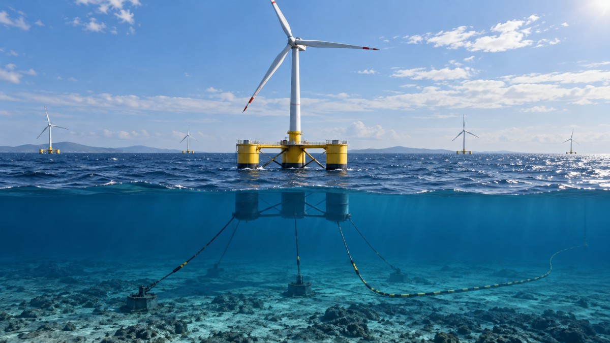
Floating offshore wind farms generate electricity using turbines mounted on buoyant structures rather than foundations fixed rigidly to the seabed. They can access wind resources in waters where fixed-bottom foundations may be impractical, but the turbine is only one part of the system. Each platform must remain stable, its moorings must restrain movement, and its subsea cables must carry power while accommodating that movement.
These components cannot be designed independently. Water depth, waves, currents, seabed conditions and the chosen installation method all affect how the platform moves and how much stress reaches the moorings and cables. A design that works in one location is not automatically suitable for another.
How a floating wind farm produces and delivers power
At the surface, a floating turbine looks much like a conventional offshore wind turbine: wind turns the rotor, which drives a generator. The difference is below the tower. Instead of transferring loads directly into a fixed foundation, the tower sits on a floating platform held in position by mooring lines connected to seabed anchors.
Electricity leaves the turbine through a dynamic cable designed to move with the platform. That cable connects into the wider collection system, which carries power between turbines and toward an offshore or onshore electrical connection. The final route to shore depends on the project’s electrical design; some projects use an offshore substation, while others have different configurations.
The system must operate as a coupled whole. Wind pushes against the rotor and tower, while waves and currents act on the platform, mooring lines and cables. The resulting motion affects power production, structural loads and maintenance access. Engineering therefore considers not just whether each component is strong enough, but how the complete system behaves over time.
What keeps the platform stable?
A floating platform must support a heavy turbine with its centre of mass high above the water, while limiting motion enough for the turbine and electrical system to operate within their design limits. Different platform concepts achieve stability in different ways.
Semi-submersible platforms
A semi-submersible generally uses several buoyant columns connected by structural members. The columns are spaced apart to provide stability, while ballast and the submerged structure help control the platform’s response to waves.
This arrangement can offer a comparatively shallow draft—the vertical distance between the waterline and the lowest point of the structure—which can be useful where ports or towing routes have limited water depth. Its suitability still depends on hull dimensions, assembly facilities, towing conditions and the site’s metocean environment.
Spar platforms
A spar uses a long, deep floating body, with ballast positioned low in the structure. Its stability comes substantially from keeping the centre of gravity low relative to buoyancy.
The deep draft is an important practical consideration. A spar may require access to deep water for final assembly or turbine integration, and the route from fabrication to the wind farm must accommodate its dimensions. A stable concept at the operating site can therefore impose substantial constraints on port and installation planning.
Tension-leg platforms
A tension-leg platform relies on buoyancy pulling upward against taut mooring tendons anchored to the seabed. The tension restrains certain vertical and rotational movements more strongly than a freely floating arrangement.
That motion control comes with demanding interfaces. Tendon tension, anchor capacity and installation sequencing are central to the design. The temporary condition before all tendons are connected also needs careful management; the platform’s behaviour during installation is not the same as its behaviour once fully secured.
These categories describe different stability principles, not a universal ranking. A platform with lower motion in one condition is not necessarily cheaper or easier to install overall. Material choice, fabrication capacity, turbine size, port access and maintenance strategy all influence the outcome.
Why floating platforms still move
“Stable” does not mean motionless. A floating structure can move horizontally, vertically and rotationally as wind, waves and currents change. Engineers assess these motions across operating, extreme and fault conditions, including circumstances when the turbine is shut down.
Movement matters because it changes the loads experienced by the turbine and its supporting equipment. For example, platform pitching changes the angle of the rotor relative to the wind and affects forces in the tower and blades. Repeated motion also contributes to fatigue: the gradual accumulation of damage caused by many load cycles, even when individual loads are below the level that would cause immediate failure.
Designers must balance motion control with other requirements. Adding ballast, changing hull geometry or modifying moorings can improve one aspect of performance while increasing structural weight, draft, anchor loads or installation complexity. The relevant question is whether the whole arrangement meets its requirements throughout its intended service life.
Moorings: holding position without fixing the platform rigidly
Mooring systems connect a floating platform to the seabed and keep it within an acceptable area. They do not generally prevent all movement. Instead, they provide restoring forces as the platform is displaced, while allowing the system to respond to environmental loads.
A mooring line may contain chain, steel wire, synthetic rope or combinations of these materials. The choice affects weight, elasticity, handling requirements and long-term behaviour. Lines connect to anchors selected for both the loads and the seabed conditions; an anchor suitable for one soil type cannot be assumed to perform equally well in another.
Two broad arrangements help explain the design trade-off:
- Catenary moorings rely on the shape and weight of hanging lines to provide restoring force. Part of a line may lie on the seabed, depending on the design and operating condition. The arrangement can require a substantial seabed footprint.
- Taut or semi-taut moorings use straighter, more tensioned lines. They can reduce horizontal footprint, but transfer different combinations of horizontal and vertical load to the anchors. Line elasticity and anchor design become particularly important.
Water depth influences the length and weight of the mooring system, but depth alone does not determine the best arrangement. Soil strength, rock conditions, available space, environmental loading and the proximity of cables or neighbouring turbines also matter. The seabed area occupied by lines and anchors can affect the layout of the entire farm.
Moorings are designed for long-term service, but they are not maintenance-free. Corrosion, wear, fatigue and changes in line tension can affect performance. Inspection plans need to account for underwater access and the difficulty of examining components at depth. A damaged line may also alter loads on the remaining lines and the dynamic cable, so the consequences extend beyond the failed component itself.
Dynamic cables: carrying power from a moving turbine
A fixed-bottom turbine has a relatively stationary cable entry point. A floating turbine moves with its platform, so the cable section connected to it must tolerate repeated bending and movement while maintaining electrical integrity.
This is the role of a dynamic subsea cable. Its design must address electrical requirements alongside mechanical loads, including bending, tension, abrasion and fatigue. The cable’s route through the water is engineered to accommodate platform movement without imposing excessive stress at its connection points.
Buoyancy modules can be attached to shape part of the cable into a controlled curve. One common configuration, often called a lazy wave, uses buoyancy to create an elevated section between the platform and the seabed. The shape helps manage movement and loads, but it must be designed for the actual water depth, currents, platform motion and cable properties.
Beyond the moving section, a cable may connect to a static cable or other subsea connection before joining the collection network. The transition between moving and less mobile sections is a critical interface: the cable must not bend too sharply or experience damaging tension as the platform moves.
Seabed conditions also matter. Where a cable lies on or approaches the seabed, designers assess contact, abrasion, burial feasibility and external hazards. The need for protection depends on the route and local risks; burial is not automatically possible or appropriate everywhere. Repair planning is equally important because a cable fault can interrupt generation and require specialized vessels, equipment and favourable weather.
How the components affect one another
A platform, its moorings and its dynamic cable share the same operating environment, but they do not respond in isolation. A change made to one can shift loads elsewhere.
Consider a design change that allows the platform more horizontal movement. This may alter mooring tensions, but it also changes the cable’s movement envelope and the space needed to keep the cable clear of mooring lines and neighbouring infrastructure. Conversely, making the station-keeping system stiffer can reduce some movements while increasing forces transmitted to anchors or the platform.
Layout decisions follow the same logic. Turbines need adequate separation for aerodynamic and electrical design, but the underwater layout must also accommodate mooring footprints, cable routes, installation corridors and future inspection or repair. Crossing constraints and seabed obstacles can make a seemingly straightforward surface layout more complicated below water.
For this reason, comparing floating concepts solely by platform dimensions or turbine capacity gives an incomplete picture. A meaningful comparison also considers the anchors, cable configuration, site conditions and work needed to install and maintain the system.
From port assembly to offshore operation
Floating turbines may be assembled at port and towed to site, reducing some offshore lifting work. Whether this is practical depends on the concept and local infrastructure. Quayside load capacity, crane reach, water depth, channel width and space for fabrication or temporary storage can all limit the assembly sequence.
At the wind farm, anchors and portions of the mooring and cable systems may be installed before a platform arrives. The platform is then positioned, connected and electrically integrated according to the project’s chosen sequence. Each connection must be completed within the operating limits of the vessels and equipment involved.
Weather affects more than the journey offshore. Towing, station-keeping, mooring hookup and cable connection each have their own limits for wind, waves and currents. A sequence that looks efficient on paper can be delayed if consecutive operations require conditions that are difficult to obtain together.
Once operating, floating turbines still require routine servicing and occasional major repairs. Some work can be performed offshore, subject to safe access and motion limits. For certain major interventions, a project may consider disconnecting and towing a unit to sheltered water or port. That option depends on the platform, mooring and electrical connections, vessel availability and suitable facilities; it should not be assumed for every design.
What makes a site suitable?
Water depth is an important reason to consider floating wind, but it is not a stand-alone threshold. Fixed-bottom and floating solutions have different engineering and cost drivers, and their relative suitability depends on the full site and project context.
A site assessment needs to establish the wind and wave climate, currents, seabed geology and available space, as well as the distance to shore and the grid connection. It must also account for other uses of the sea and the requirements of the relevant permitting process. A strong wind resource is valuable, but it does not remove the need for workable anchors, cable routes, port facilities and maintenance access.
The clearest way to understand a floating wind farm is therefore as an integrated offshore system. Its platform provides buoyancy and stability; its moorings keep it on station; and its dynamic cables deliver power while accommodating movement. Their performance depends on how well those functions are matched to one another and to the conditions in which the farm will be installed and operated.
Tag
Recommended for You
{item.title}
News Categories
Leave Us a Message