
Performance Benchmarks
Offshore Wind Farm Wake Effects: How Turbine Spacing Affects Yield
Offshore wind farm wake effects reduce energy yield when upstream turbines slow the wind and alter turbulence for machines downstream. Increasing turbine spacing can reduce those losses, but it also changes the area occupied by a project and may increase cable length, electrical losses and installation costs. The best layout is therefore not the one with the lowest wake loss in isolation, but the one that delivers an acceptable balance of energy, cost and uncertainty within the site’s constraints.
No single spacing rule resolves that balance. Wind direction, atmospheric stability, turbine operating behavior and the presence of neighboring wind farms all affect how much additional energy a wider layout can produce. A spacing comparison is meaningful only when those conditions, the energy calculation and the project boundary are defined consistently.
Why distance between turbines changes energy yield
A turbine extracts momentum from the wind, leaving a region of lower average wind speed downstream. The wake expands and gradually recovers as surrounding air mixes into it. A downstream rotor exposed to that wake receives less kinetic energy than it would in undisturbed flow. Because wind power is strongly dependent on wind speed below rated output, even a modest speed deficit can produce a material reduction in energy under those conditions.
Recovery is not governed by distance alone. Ambient turbulence, atmospheric stability and the operating state of the upstream turbine affect both the wake deficit and its spread. A rotor can also be only partly immersed in a wake, making lateral separation important as well as distance along the wind direction.
Spacing is commonly expressed in rotor diameters, or D. For a turbine with a 200-meter rotor, a center-to-center distance of 1,400 meters corresponds to 7D. This normalization is useful for comparing layouts with different rotor sizes, but it does not make their wake behavior identical: thrust, power curve and control strategy also matter.
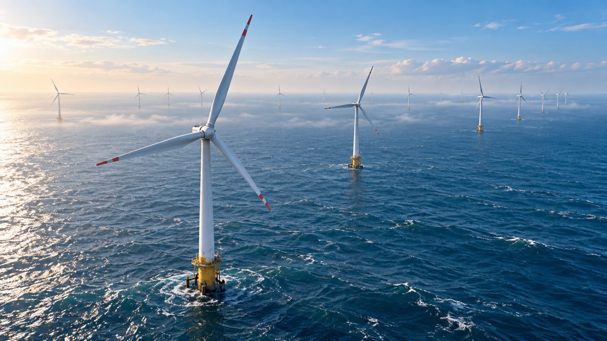
A layout should be evaluated across the full distribution of wind directions, not just its prevailing direction. Turbines arranged in neat rows can experience strong alignment losses when wind follows a row. A small directional shift may reduce direct overlap, while another wind sector places a different set of turbines in line. Rotating or staggering rows can redistribute these losses, although the benefit depends on the site’s wind rose and boundary shape.
What wider spacing does—and does not—guarantee
Increasing separation in the prevailing wind direction generally gives individual wakes more distance to recover before reaching the next rotor. Increasing crosswind spacing can reduce overlap for some directions. Neither change guarantees a better project outcome: a wider layout may place turbines in less favorable wind resource areas, increase exposure to neighboring wakes or require a longer collection system.
The comparison also depends on what is held constant:
- Fixed turbine count and capacity: spreading turbines across a larger area can improve energy per turbine, subject to wind resource variation and external wakes, but may increase infrastructure and seabed requirements.
- Fixed site boundary: wider spacing may require fewer turbines. Wake loss as a percentage can fall while total annual production also falls because installed capacity has been reduced.
- Fixed total capacity: layouts with different turbine sizes or counts must be assessed using the appropriate power and thrust curves; a comparison based only on spacing in rotor diameters is incomplete.
These distinctions matter when reviewing a reported wake-loss percentage. A lower percentage does not automatically mean more megawatt-hours. Nor does higher gross production establish the best financial result if the gain requires disproportionately greater cable, foundation or installation expenditure.
Atmospheric conditions can change the ranking of layouts
Offshore wakes can persist over substantial distances, particularly when the atmosphere is stable and vertical mixing is limited. Under more turbulent conditions, mixing can accelerate wake recovery, although the added turbulence has its own implications for turbine loading. A model calibrated to one set of atmospheric conditions may therefore overstate or understate the benefit of spacing under another.
Wind direction and speed should be represented together with the conditions that influence wake recovery. Using a long-term wind rose with a single assumed turbulence intensity can obscure whether the highest wake losses occur during frequent, productive wind conditions or during less important periods. Stability-sensitive analysis is especially relevant when competing layouts differ mainly in closely aligned rows.
The turbine power curve is another important boundary. Below rated wind speed, a wake-induced reduction in speed generally reduces power. Near and above rated output, the relationship can be different because a turbine may already be producing at or near its rated power. Wake effects on annual energy must consequently be integrated across the wind-speed distribution rather than inferred from a single wind speed.
Internal wakes are only part of the flow field
A proposed wind farm can receive wakes from existing or planned projects outside its boundary, and its own turbines can affect projects farther downwind. These external effects depend on relative location, wind direction and the operational status of neighboring capacity. A spacing study that excludes neighboring farms can attribute too much value to an internal layout change if incoming wind is already disturbed.
External-wake scenarios should distinguish operating turbines from projects that are consented, proposed or uncertain. Assuming every announced project is operating throughout the evaluation period can be as misleading as assuming none will be built. Where neighboring development is material, a comparison can report a base case and alternative build-out cases rather than presenting a single external-wake number as certain.
Large arrays also alter the flow at farm scale. The combined extraction of momentum can influence turbines beyond those directly behind an individual machine, and flow approaching a farm may be affected by the array itself. The significance of these effects depends on the site and modeling method. They should not automatically be treated as the same thing as the sum of individual turbine wakes, nor added as separate losses without checking for overlap or double counting.
Comparing wake models on a consistent basis
Engineering wake models are useful for screening and optimizing layouts because they can evaluate many turbine positions and wind conditions efficiently. Their simplifications become important when the decision turns on a small difference between options. Model choice, wake expansion assumptions, treatment of partial overlap and methods for combining multiple wakes can all affect the predicted result.
A defensible comparison starts with common inputs: the same wind resource, turbine specifications, availability assumptions and calculation period for each layout. The analyst should identify whether the model uses hub-height conditions or a description of the flow across the rotor, and how it represents changes in thrust with wind speed. If different turbine models are compared, each requires its own power and thrust information.
The output should make the energy accounting visible. A useful separation is:
- Gross energy: energy calculated before the specified project losses, with the definition of the gross baseline stated.
- Wake-adjusted energy: energy after modeled wake effects, identifying whether internal and external wakes are included.
- Net energy: energy after the other applicable losses and constraints, with electrical losses, availability and curtailment treated consistently.
Loss percentages cannot be compared reliably if one is calculated against gross energy and another against an already reduced baseline. Nor should wake losses be added mechanically to other percentage losses without checking the order and basis of calculation.
Where measurements are available, model validation should focus on conditions relevant to the layout decision: wind sectors that align turbine rows, wind speeds with high energy contribution, and the atmospheric conditions under which wakes persist. Measurements of a different turbine type or a different offshore environment can inform model selection, but they do not by themselves validate a site-specific prediction.
How much confidence is needed in the predicted gain?
Suppose a wider layout shows a small modeled energy improvement but requires longer inter-array cables. The key question is whether the energy difference is robust to credible changes in the assumptions, not simply whether the preferred model produces a positive number. Sensitivity cases can vary wake recovery, wind direction distribution, turbulence and external-farm build-out while keeping the comparison internally consistent.
Uncertainty in the difference between layouts is not necessarily the same as uncertainty in either layout’s absolute energy estimate. Some input errors affect both options in a similar way and partly cancel; others, such as errors in wind directions that align one layout’s rows more strongly, can change their ranking. Reporting only a single overall uncertainty figure can hide this distinction.
Higher-fidelity flow modeling or additional measurements are most valuable when they can resolve a decision. They may be justified where layout rankings change across plausible assumptions, where external wakes are influential, or where a modest energy difference carries a substantial infrastructure cost. More detailed modeling still requires appropriate inputs and validation; greater complexity alone does not establish greater accuracy.
From wake loss to a workable layout decision
Spacing affects the collection system as well as the flow field. Greater distances can increase cable route length and electrical losses, but the actual effect depends on turbine positions, string configuration, substation location, cable ratings and routing constraints. Straight-line distances between turbines are not a substitute for an engineered cable layout, particularly where exclusions or seabed conditions require detours.
Foundation positions, installation sequencing and maintenance access also constrain feasible arrangements. A layout with attractive aerodynamic performance may be impractical if it places turbines in unsuitable ground conditions or conflicts with navigation, cable crossings or lease boundaries. Conversely, a compact layout may fit a constrained area but carry higher wake losses and wake-added turbulence, which should be considered in the load assessment as well as the energy estimate.
The most useful result is therefore a comparison of feasible layouts using both net energy and the costs directly affected by layout. The evidence should show the energy baseline, wind and turbine inputs, treatment of neighboring farms, wake-model assumptions and sensitivity of the ranking. If the predicted advantage disappears under reasonable alternative assumptions, the apparent precision of a single wake-loss percentage is not enough to support the spacing decision.
Tag
Recommended for You
{item.title}
News Categories
Leave Us a Message