Subsea Cables
What causes subsea cables to fail at crossings?
Subsea cables face concentrated mechanical and operational risks where they cross existing cables or pipelines. A crossing introduces interfaces that are absent along much of the route.
Inadequate separation, seabed movement, poorly installed protection systems and damage during installation or maintenance can increase the likelihood of failure.
For technical evaluators, the critical question is not simply whether a crossing is protected, but whether its design, installation tolerances and long-term stability suit local conditions.
This article examines the main failure mechanisms and the evidence needed to assess crossing risk, from initial survey and design through installation, inspection and repair.
Why are subsea cable crossings vulnerable to failure?
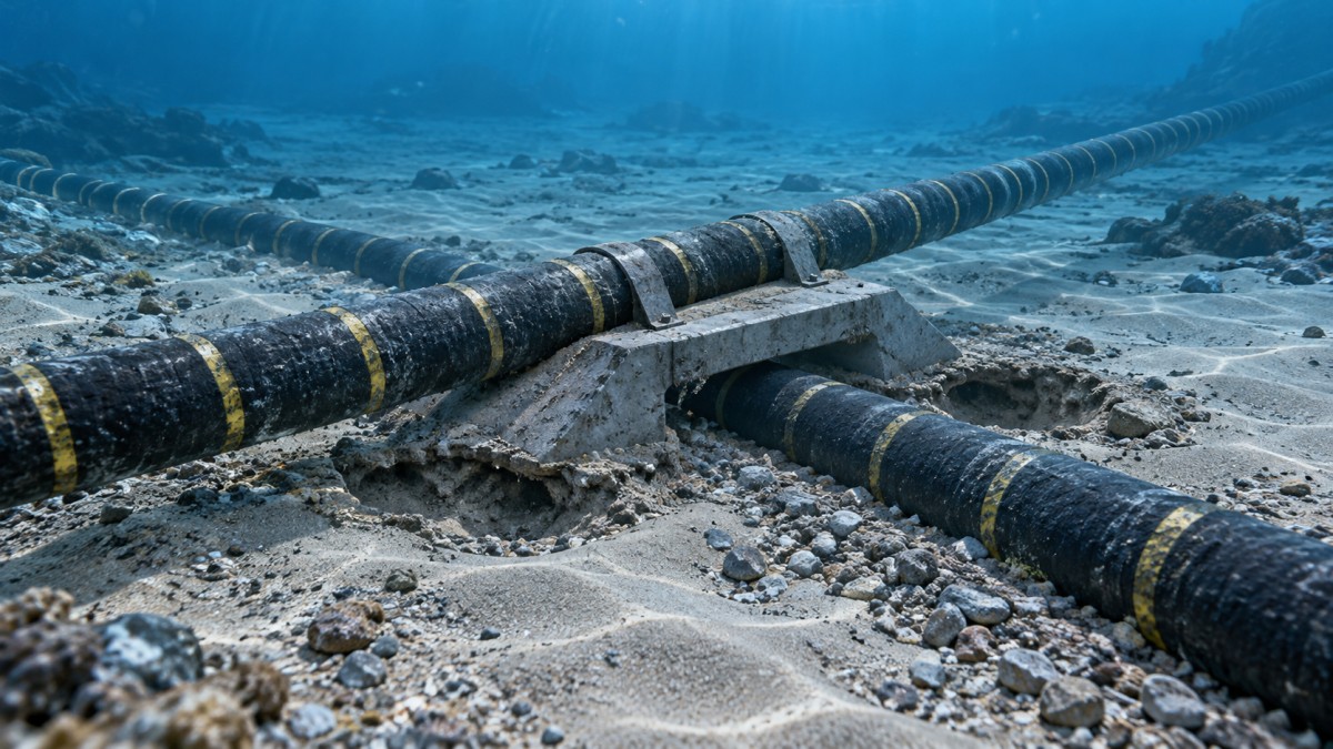
A crossing concentrates changes in elevation, support and stiffness into a short section of cable. Those changes can create local loading that is difficult to see after installation.
Failure rarely follows from the crossing angle or separation distance alone. More often, several conditions combine, such as uncertain seabed levels, uneven protection and later sediment movement.
The consequences depend on the assets involved. Cable-to-cable crossings raise electrical and thermal questions, while cable-to-pipeline crossings also require attention to pipeline integrity and access.
A sound evaluation therefore checks the complete arrangement: both assets, the seabed, protective materials, installation equipment, operating loads and the ability to intervene later.
Protection can reduce contact and external damage, but it can also introduce hard edges, uneven support or additional loading if its geometry and placement are unsuitable.
How can poor separation and support damage a cable?
Insufficient separation can allow direct contact between assets or between a cable and an unsuitable protective surface. Movement under load can then cause abrasion or concentrated pressure.
Separation must remain effective after installation, not just appear adequate on a design drawing. Settlement, scour and placement tolerances can change the as-built geometry.
Where a cable passes over a raised protection layer, it may lose continuous support on the approach. The resulting free span can increase bending and cyclic loading.
Abrupt changes in support elevation can also force the cable into a tighter bend than intended. Excessive bending may damage internal layers or reduce fatigue life.
Conversely, a very stiff protection arrangement may transfer loads to a short section of cable. The transition between protected and unprotected seabed deserves particular attention.
Evaluators should request drawings showing actual elevations, gradients, contact surfaces and tolerances, together with calculations demonstrating compliance with the cable manufacturer’s installation and operating limits.
What role do seabed movement and scour play?
Currents and waves can remove sediment around a crossing, leaving a cable or protection structure less supported than assumed. The risk depends on local hydrodynamics and sediment behavior.
Scour may develop beside mattresses, rock berms or exposed pipelines. Even when the protection remains in place, erosion at its edge can create a damaging span.
Soft seabeds present a different concern: protection may settle unevenly, altering separation or imposing loads on an existing asset. Settlement can continue after installation is complete.
Mobile seabed features can bury one part of a crossing while exposing another. A single survey may therefore describe a temporary condition rather than long-term stability.
Assessments should use site-specific bathymetry, geotechnical information and metocean data. Where relevant, they should also consider sediment mobility and the performance of nearby installed structures.
Ask whether the design addresses plausible changes over its intended life, including the limits of available data. Inspection triggers and intervention options should follow from those uncertainties.
Can crossing protection itself cause cable failure?
Protection systems may include engineered rock placement, concrete mattresses or other separation and stabilization products. Their suitability depends on both assets and the installation environment.
Incorrectly placed rock can create uneven support or expose the cable to localized contact. The specified grading, placement method and final profile all influence the result.
Mattresses can leave gaps, overlap unevenly or settle differently across the crossing. Edges and lifting arrangements also require assessment where they could interact with the cable.
A protection product’s nominal dimensions do not prove its installed performance. Actual coverage, tolerances, seabed conformity and compatibility with the cable must be demonstrated.
More protection is not automatically better. Additional material can increase loading, complicate heat dissipation or make future access harder, depending on the crossing design.
Review the protection design as an integrated system, including installation sequencing, expected deformation and the consequences if individual units are misplaced or damaged.
How do installation errors create crossing failures?
A cable can be damaged before the crossing enters service. Excessive tension, uncontrolled bending, contact with equipment or an inaccurate touchdown position are important installation hazards.
Position uncertainty matters at several stages: locating the existing asset, placing separation material, laying the new cable and installing any final protection layer.
If those tolerances accumulate in the same direction, a design that appears acceptable on paper may leave inadequate coverage or separation in the field.
Installation procedures should identify hold points, survey requirements, equipment operating limits and actions when actual conditions differ from the approved design.
For a cable-to-pipeline crossing, the method should also address the existing pipeline’s allowable external loads and the precautions required by its owner and applicable permits.
As-built evidence should include positioning data, observed geometry, placement records and documented deviations. An unresolved deviation is an engineering issue, not merely an administrative omission.
Do electrical and thermal effects matter at crossings?
Yes. Mechanical integrity is central, but electrical and thermal interactions can also affect suitability. Their significance depends on cable design, loading and the crossing arrangement.
Heat generated by operating power cables must dissipate through surrounding materials. Additional burial or protection can change thermal resistance and affect the allowable operating current.
A thermal assessment should use representative loading, material properties, geometry and environmental assumptions. It should also consider uncertainty where installed conditions differ from the design.
Electrical interference and induced effects may require assessment, especially where assets operate at different voltages or have different bonding and protection arrangements.
For pipeline crossings, relevant studies may include induced voltage and corrosion-control interactions where the electrical configuration and operating conditions warrant them.
Evaluators should seek calculations and agreement between asset owners rather than assume that a standard separation detail resolves every thermal or electrical interface.
How can maintenance and repair damage an otherwise sound crossing?
Future work near a crossing can disturb protection or expose an existing cable. Hazards include excavation, mattress removal, lifting operations and the placement of replacement material.
Accurate records are essential because the repair contractor may work years after installation, using different vessels, equipment and personnel from the original project.
A repair strategy should identify ownership boundaries, access restrictions and the process for agreeing temporary support or protection with the other asset owner.
Practical access also matters. A crossing may be technically stable but difficult to inspect or repair because protective material cannot be removed without unacceptable risk.
Check whether contingency planning covers likely repair scenarios, including equipment availability, seabed conditions, permits and the possible need to interrupt another asset’s operation.
What evidence should technical evaluators request?
A credible assessment connects design assumptions to verified installation and ongoing monitoring. Request the following evidence in a form that allows both asset owners to review it.
- Asset information: Verified locations, dimensions, burial status, operating conditions, allowable loads and relevant limitations for both existing and proposed assets.
- Site data: Survey coverage, seabed levels, geotechnical properties, metocean conditions and evidence supporting assumptions about scour, sediment movement and settlement.
- Engineering analysis: Crossing geometry, separation, bending, support, stability and applicable thermal or electrical studies, including sensitivity to installation tolerances.
- Installation documentation: Approved procedures, equipment limits, positioning methods, inspection hold points, contingency measures and responsibilities for resolving deviations.
- As-built verification: Survey records, protection placement data, observed cable position, accepted deviations and confirmation that the installed arrangement meets design requirements.
- Lifecycle arrangements: Inspection responsibilities, condition-based intervention criteria, repair access, asset-owner agreements and records available to future contractors.
The required depth of analysis should reflect consequences and uncertainty. A complex crossing with limited seabed data warrants closer scrutiny than a well-characterized, low-consequence arrangement.
Applicable standards, permits and crossing agreements should be checked for the project jurisdiction and asset types. Their requirements do not replace site-specific engineering judgment.
Which warning signs deserve escalation?
Escalate a crossing for further review when existing asset positions are uncertain, survey data are outdated or the proposed installation tolerances consume the available design margin.
Other warning signs include unexplained free spans, steep protection transitions, conflicting seabed assumptions, unverified thermal properties or a repair plan that depends on unproven access.
Missing as-built records are particularly important. Without them, operators may be unable to distinguish a compliant installation from one that only follows the intended layout approximately.
Where evidence is incomplete, the appropriate response may be additional survey, revised analysis, modified protection or a defined inspection regime, depending on the risk.
Conclusion: assess the crossing over its full life
Subsea cable failures at crossings can result from concentrated mechanical loads, changing seabed support, unsuitable protection, installation errors or later intervention. Thermal and electrical interfaces may also matter.
The strongest assessment demonstrates that separation, support and protection remain appropriate across expected conditions, including installation tolerances and credible changes during operation.
For technical evaluators, the decisive question is whether design calculations, as-built evidence and lifecycle responsibilities support the same conclusion. A protection detail alone is not enough.
- Last One:Offshore Wind Grid Connection: HVAC vs HVDC for Distant Projects2026-11-12
- Next Article:No more articles
Tag
Recommended for You
{item.title}
News Categories
Leave Us a Message