Installation Vessels
Choosing wind turbine installation vessels for deep water
Selecting Wind Turbine Installation Vessels for deep-water projects requires more than comparing crane capacity and day rates. Water depth, seabed conditions, metocean limits, station-keeping capability, deck space and port interfaces can all influence whether a vessel is technically suitable and commercially viable. The most useful comparison starts with the intended installation sequence, then tests each vessel against the loads, motions and interfaces it will actually encounter.
“Deep water” is not, by itself, a vessel specification. A site may be beyond the practical reach of one jack-up yet accessible to another, depending on leg length, air gap, seabed penetration and operating restrictions. Equally, a floating vessel that can reach the site is not automatically capable of installing every turbine component there.
Start with the installation concept, not the vessel brochure
Define what the vessel is expected to install: fixed-bottom foundations, turbine components, pre-assembled units, or equipment associated with floating wind. These duties produce different lift heights, outreach requirements and tolerances. For floating wind, the concept may involve quayside turbine assembly followed by tow-out, rather than offshore installation of each tower section, nacelle and blade. Mooring and cable work may then require a different spread of vessels.
The boundary between vessel scopes matters. A heavy-lift vessel may place a foundation while another vessel installs the turbine; alternatively, one vessel may perform several tasks but require additional mobilization or changes to its deck arrangement. Compare complete sequences, including transfers, waiting time and handovers, rather than assuming that fewer vessels always means fewer risks.
For an initial screening package, evaluators need the component weights and centres of gravity, dimensions, lift points, target installation elevations, site coordinates, water depths, seabed information and the proposed construction season. If these inputs are provisional, identify which vessel conclusions depend on them. A preliminary lift study is only as reliable as its load data.
Jack-up or floating vessel: where the decision turns
A jack-up provides an elevated working platform after its legs are deployed and the hull is raised clear of the water. That can reduce vessel-motion effects during turbine lifts, but it introduces a demanding seabed interface. The review must cover leg length, hull elevation, required air gap, leg penetration, preload arrangements and the range of site depths—not just a single advertised maximum water depth.
Geotechnical conditions can make otherwise suitable locations difficult. Uneven penetration, punch-through potential, slopes, boulders or obstructions may require further analysis or a revised positioning plan. Existing cables, foundations and exclusion zones also constrain where legs can be placed. A vessel’s generic seabed capability does not replace site-specific geotechnical assessment.
A floating heavy-lift vessel avoids jacking onto the seabed and may offer greater flexibility where water depth or ground conditions rule out a jack-up. The trade-off is that vessel motion becomes part of the lift. Dynamic positioning, mooring arrangements, crane behavior and load control must be assessed together. In particular, the feasibility of bringing a suspended component into alignment with a tower or foundation connection can govern the operation more than the lift itself.
Neither category should be declared the winner before the task is defined. A floating vessel suitable for foundation installation may not have the motion limits, lift height or handling systems needed for individual blade installation. Conversely, a jack-up selected for turbine work may face leg-positioning restrictions that make a separate foundation vessel the safer choice.
Check the crane at the real lift geometry
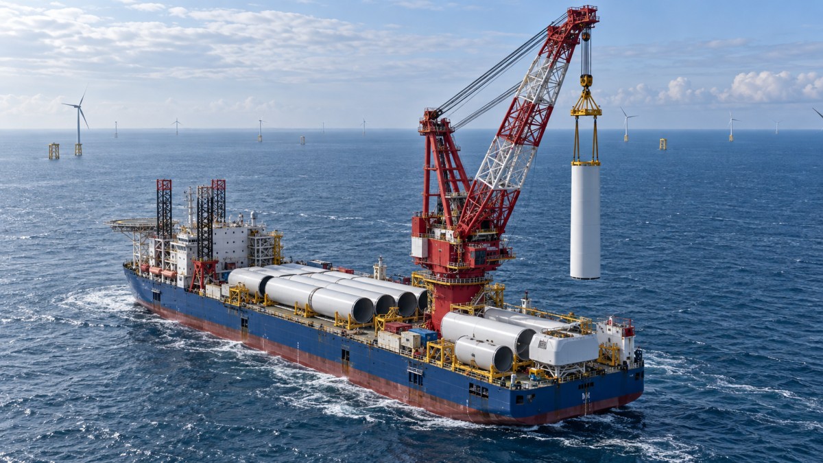
Headline crane capacity is a starting point, not an acceptance criterion. Request the applicable load chart and check capacity at the required radius and hook height, with the relevant boom configuration. Include rigging, lifting frames, hooks and any other suspended equipment in the lifted load. Confirm whether the quoted capacity and the proposed method account for the dynamic effects applicable to the operation.
Outreach often changes during the lift. A component may need to clear cargo on deck, move past the vessel structure and land at a position that is not directly alongside the crane. For a floating vessel, relative motion between the vessel, suspended load and receiving structure must also be considered. A lift that works on a static drawing may prove restrictive once operational clearances and motions are included.
Blade handling deserves separate attention. Weight alone says little about the difficulty of controlling a long, wind-sensitive component. Ask how orientation will be managed, what clearances are needed, and which wind and motion limits apply to the proposed handling system. For tower and nacelle lifts, check mating tolerances, access for bolting and the time needed to secure the component before releasing the crane.
Deck capacity is a layout problem
Total deck area or payload can make two vessels appear comparable when their usable arrangements are very different. Evaluate local deck loading, grillage and sea-fastening locations, component overhang, crane access and the path from stowage position to lift-off. The vessel may also need space for lifting tools, spare equipment, walkways and emergency access.
A useful test is to draw the actual cargo plan for each sailing. Can the first component be removed without disturbing the others? Does the installation sequence match the order in which components are accessible? If a turbine set requires rehandling offshore, the apparent benefit of carrying more cargo may disappear into additional crane time and exposure.
Confirm who designs, supplies and removes the grillage and sea fastenings, and whether deck modifications affect vessel approvals or mobilization time. These interfaces are easy to leave between contracts until the schedule becomes tight.
Station-keeping and weather limits must match each operation
For a dynamically positioned vessel, review the station-keeping assessment for the proposed location and task, including environmental conditions, heading, thruster configuration, power availability and relevant failure scenarios. The question is not simply whether the vessel has dynamic positioning, but whether it can maintain the required position while conducting the lift or transfer. Any project-specific assurance and redundancy requirements should be agreed with the appropriate marine and technical authorities.
A moored vessel has a different set of constraints: anchor deployment, line lengths and clearances must be compatible with water depth, seabed infrastructure, other vessels and the installation sequence. Mooring analysis should account for both planned operations and credible changes in conditions.
Weather limits should be broken down by activity. Transit, jacking, lifting, blade mating and personnel transfer can each have different limiting conditions. A forecast window must cover the operation and any required contingency or safe stopping point; it is not enough for conditions to be acceptable at the moment a lift begins.
When comparing weather downtime estimates, ask for the location, historical period, seasonal assumptions, forecast rules and operation durations used. Two estimates can disagree because they model different decision rules rather than because one vessel is inherently better. Also distinguish a supplier’s stated limit from a limit demonstrated for the specific component, lifting arrangement and site.
The port can decide whether the vessel works
A technically capable vessel may be difficult to use if it cannot enter the marshalling port at the required draft or tide, berth safely, or load components within the available crane outreach. Check channel restrictions, turning areas, quay bearing capacity, water depth alongside, air draft where relevant, and the interface between vessel and shore cranes.
Port readiness also affects the installation cycle. Component storage, transport routes, pre-assembly space, shore-side power and the timing of deliveries can determine whether the vessel loads as planned. If the proposed alternative relies on a different port, include the additional transit and logistics in the comparison rather than treating them as someone else’s problem.
Local rules on vessel operations, personnel, permitting and environmental controls should be checked for the actual jurisdiction and contract scope. Do not assume that a method accepted on a previous project can be transferred unchanged.
Compare delivery risk, not just the day rate
Build the commercial comparison around a common installation schedule. Include mobilization and demobilization, port time, transit, loading, offshore operations, expected weather exposure, support vessels, specialist equipment and demobilization of temporary works. Identify which costs are included in the vessel offer and which remain with the project.
A lower daily rate may be outweighed by an extra sailing, a restrictive lift window or a long mobilization. A higher-rate vessel may still be a poor choice if it depends on a crane upgrade or handling tool that has not been delivered. Availability should be assessed as a contractual and operational question: distinguish a proposed vessel or modification from equipment already delivered, tested and available for the required period.
Pay attention to the allocation of delay risk. Weather standby, breakdowns, late components, port unavailability and changes to lift weights may be treated differently in each offer. The technical team should understand those boundaries before ranking bids; otherwise, a schedule assumption can quietly become a commercial exposure.
Evidence to request before selecting a vessel
The strongest bid is not necessarily the one with the longest reference list. Ask for evidence that corresponds to the proposed duty, and separate completed offshore work from planned upgrades or supplier claims. The following documents make a practical starting point:
- Vessel particulars, current crane charts and a project-specific lift assessment, including rigging and operating assumptions.
- A cargo layout and preliminary sea-fastening concept for the actual components and loading sequence.
- For jack-ups, leg and jacking data plus the information required for site-specific geotechnical and positioning studies.
- For floating vessels, relevant station-keeping or mooring assessments and the motion assumptions used for critical lifts.
- Activity-specific operating limits, weather-window methodology and the proposed response if conditions deteriorate.
- A mobilization plan, equipment availability, crew and specialist support arrangements, and the status of any modifications.
Record unresolved assumptions alongside the vessel ranking. If hub height, component weight, ground conditions or port access change, revisit the affected lift and schedule studies before treating the selection as final. The best choice is the vessel whose complete installation method remains workable under the project’s actual constraints—not the one with the most impressive specification sheet.
- Last One:Should You Sign a Long-Term Cable Repair Vessel Agreement?2026-11-12
- Next Article:No more articles
Tag
Recommended for You
{item.title}
News Categories
Leave Us a Message