
Offshore Wind Installation
Optimizing Offshore Wind Farm Layouts for Energy Yield and Cable Costs
For most offshore wind projects, the layout with the highest predicted energy yield is not automatically the best investment. Moving turbines farther apart can reduce wake losses, but it can also lengthen array cables, increase electrical losses, complicate installation and change the capacity required elsewhere in the electrical system. A defensible choice compares those effects over the project’s life, under the same site and commercial assumptions.
The balance depends on the shape of the lease area, wind direction and speed distributions, seabed conditions, turbine characteristics and the position of offshore substations. Offshore wind farm layout optimization is therefore most useful when turbine placement and cable design are evaluated together, rather than when one discipline receives a fixed layout from the other.
Start with the energy value of each turbine position
A turbine changes the wind reaching machines downstream. The resulting wake can reduce production and increase turbulence, with consequences for loading and maintenance as well as annual energy output. The size of the effect varies with wind speed, direction, atmospheric conditions, turbine operation and the position of neighboring turbines.
Spacing turbines more widely along a frequent wind direction may improve energy capture, but a single prevailing direction rarely describes the whole site. A layout that performs well in one sector can create long rows of wakes in another. Evaluators should examine the wind distribution by direction and speed, including how much energy each sector contributes, rather than optimizing against the most frequent direction alone.
Model assumptions matter especially when candidate layouts differ by a small margin. Ask whether the assessment uses site-representative wind measurements, how uncertainty in the wind resource is treated and whether wake model settings are appropriate for the turbine and site. Comparisons should use the same resource data, turbine power curve, availability assumptions and calculation period. Otherwise, an apparent layout improvement may come from a change in inputs rather than a better design.
Energy yield should also be assessed beyond gross turbine production. Array cable losses, electrical availability, curtailment and other relevant deductions affect the energy delivered to the point used for commercial evaluation. The location of that accounting point must be consistent across options; energy calculated at turbine terminals is not directly comparable with energy calculated after electrical losses.
Wake performance is not limited to production. A candidate with a modest yield advantage may expose particular turbines to higher turbulence or uneven loading. Those effects require engineering assessment against the selected turbine’s design assumptions. They should not be converted into a precise maintenance saving or penalty unless the supporting evidence is sufficient.
Cable length is only the first part of cable cost
A compact turbine arrangement can shorten connections, but total installed cost depends on the electrical topology and the route each cable can actually follow. Straight-line distance between turbines is an early screening measure, not a construction route. Seabed obstructions, ground conditions, crossings, exclusion areas and required separation from other infrastructure can all force deviations.
Electrical configuration also affects the comparison. The number of turbines connected along an array string, cable conductor sizes and substation location influence both capital cost and losses. A longer route may require a different cable size or create higher resistive losses; a shorter route may be constrained by string capacity or the way connections must enter the substation. Cable ratings must be assessed for the intended installation conditions, including burial and the thermal characteristics of the surrounding material.
Installation cost can move independently of route length. A longer route through suitable ground may be preferable to a shorter route that needs extensive preparation or additional protection. Conversely, avoiding a difficult section by rerouting can add cable, crossings or installation time. The comparison should include the proposed burial method, achievable burial depth, protection requirements and the uncertainty in ground conditions, not just a cost per kilometer.
Repair access is another layout variable. A route that is technically installable may be harder to retrieve, repair and re-lay if it passes close to foundations, crosses other assets or enters a congested substation approach. These constraints should be identified before treating a cable route as a low-cost option.
Where the trade-off changes direction
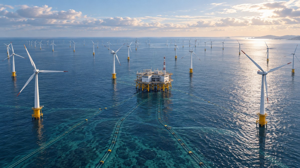
Consider two feasible layouts within the same lease area. The first spreads turbines farther apart and produces a higher modeled annual yield. The second groups them more tightly around the substation, reducing the initial array cable requirement but increasing wake losses. Neither result is decisive until the additional delivered energy from the first layout is valued against its additional lifetime cost and risk.
The comparison can change with the shape of the site. In a long, narrow area, improving spacing in one direction may push turbines farther from the substation or leave little room to avoid wakes in another direction. In an irregular area with seabed exclusions, the positions that look best aerodynamically may create cable detours or difficult crossings. A central substation can reduce some routes but may have its own foundation, installation or access constraints.
The substation position should therefore be tested alongside turbine positions when the design still allows it. Fixing it too early can hide a better combined solution; allowing it to move without recognizing its structural, electrical and installation constraints can produce an impractical one. The same applies to turbine count: adding a machine may increase gross output while changing wake losses, cable string design and export limitations for the rest of the farm.
The most useful output is often a set of credible alternatives rather than a single numerical winner. One design may offer higher expected yield, another lower upfront expenditure and a third better resilience to uncertain seabed conditions. The preferred option depends on which differences remain material after uncertainty and delivery constraints are included.
Compare alternatives on a consistent economic basis
A layout assessment should trace the difference between candidates from physical design to financial result. At minimum, the comparison needs the same project boundary, operating period, price assumptions and treatment of financing and discounting. If an option shifts costs outside the modeled boundary, such as from array installation to later cable protection, the apparent saving can be misleading.
A practical evaluation brings together:
- Delivered energy: expected annual output after the same wake, electrical loss, availability and curtailment assumptions, with uncertainty shown separately.
- Electrical capital cost: cable lengths and sizes, accessories, connections, protection and any changes to substations or other equipment included in the design boundary.
- Installation exposure: route preparation, burial or protection methods, crossings, vessel requirements and schedule assumptions.
- Operating consequences: losses over the operating period, access for inspection and repair, and any supported differences in reliability or maintenance.
- Residual design uncertainty: unresolved wind-resource, wake, seabed or installation assumptions that could change the ranking.
Levelized cost of energy can provide a common measure, but it should not be the only decision metric. It compresses many assumptions into one figure and may not reflect the value of when energy is produced. A project’s financial model may place different values on output at different times, while an investor may also need to examine cash flow, funding requirements and downside exposure. Whatever metric is used, evaluators should be able to see the underlying energy, cost and risk differences.
Avoid counting the same effect twice. For example, electrical losses should either reduce the energy used in the financial calculation or be valued separately on a consistent basis. Similarly, a contingency for difficult burial should not be added again as a separate risk allowance without identifying the overlap.
Test whether the preferred layout is robust
An optimized result is only as credible as the assumptions that distinguish it from the alternatives. Sensitivity analysis should focus on variables capable of changing the decision: wake behavior, wind direction distribution, cable route length, seabed conditions, installation productivity, energy value and the cost of capital. Each test should state what changed and whether the candidate designs were re-evaluated on the same basis.
Some uncertainties are linked. A change in turbine position can alter both wake performance and cable routing; a revised route can affect installation cost, losses and repair access. Testing each input in isolation is useful for understanding its influence, but combined scenarios are needed when changes plausibly occur together.
Design maturity also determines how much confidence to place in the ranking. An early study may use indicative cable routes and broad seabed assumptions to eliminate clearly unattractive configurations. A later decision should use more developed routing, electrical sizing and site investigation evidence. If the difference between two layouts is smaller than the uncertainty in those inputs, selecting the apparent numerical winner may be premature.
For technical evaluators reviewing an optimization study, the request is straightforward: obtain the candidate coordinates and constraints, the wind and wake assumptions, the electrical topology, route basis, cost boundary and sensitivity results. The preferred configuration should remain feasible when those assumptions are challenged, and its claimed advantage should be traceable to identifiable changes in delivered energy, cost or exposure. That evidence is more valuable than an optimized layout presented as a single percentage improvement.
- Last One:No more articles
- Next Article:How turbine size affects offshore wind installation methods2026-11-12
Tag
Recommended for You
{item.title}
News Categories
Leave Us a Message