Offshore Wind Installation
How turbine size affects offshore wind installation methods
As offshore wind turbines grow in size, installation methods must adapt to heavier components, greater lifting heights, and changing vessel and port requirements. For project managers, these shifts can affect installation sequencing, weather windows, procurement schedules, and overall delivery risk. The decisive question is not simply whether a vessel can lift the largest component. It is whether the complete installation system can handle every component, at the required height and radius, under the conditions expected at the site.
Turbine rating is not an installation specification
A turbine’s rated capacity is a useful description of its electrical output, but it is a poor standalone measure of installation difficulty. Two machines with similar ratings can have different nacelle masses, tower arrangements, blade lengths, lifting points and assembly procedures. A change in hub height can make a previously suitable crane unusable even when the heaviest lift remains within its nominal capacity.
The project team therefore needs a component-level installation envelope early in development. It should include transport and lifting masses, dimensions, centres of gravity, approved lifting points, rigging requirements, target elevations and manufacturer restrictions. These figures must be controlled as the turbine design matures: a late change to a tower section or nacelle interface can affect deck layout, crane radius and the vessel reservation.
Size also changes the economics of the whole farm. Larger turbines can mean fewer units for a given project capacity, potentially reducing the number of tower erections and electrical connections. That does not automatically mean a shorter installation campaign. A vessel may carry fewer sets per trip, individual lifts may require more restrictive conditions, or the port may need modifications before the first shipment arrives.
Crane capacity must be checked at the actual lift geometry
A crane’s headline lifting capacity is not the capacity available for every offshore operation. The relevant value comes from the applicable load chart at the required working radius, boom configuration and hook height. The lifted load includes not only the component but also rigging, lifting beams, hooks and other equipment accounted for under the project’s lifting method.
For a nacelle lift, the crane may need to reach across the deck and over an erected tower. The team must check clearance between the boom, tower, component and rigging throughout the lift, not just at the final position. Blade installation presents a different problem: a blade may be lighter than a nacelle, yet its length, aerodynamic behaviour and need for precise alignment can determine the operating limit.
Lift planning also needs to consider dynamic effects and the limits specified for the vessel, crane, lifting equipment and turbine component. An upgrade that increases hook height or capacity may change stability, deck loading, leg loads or operational limits. A proposed modification is not equivalent to a completed and accepted upgrade; its engineering, certification where applicable, and delivery schedule belong in the project risk assessment.
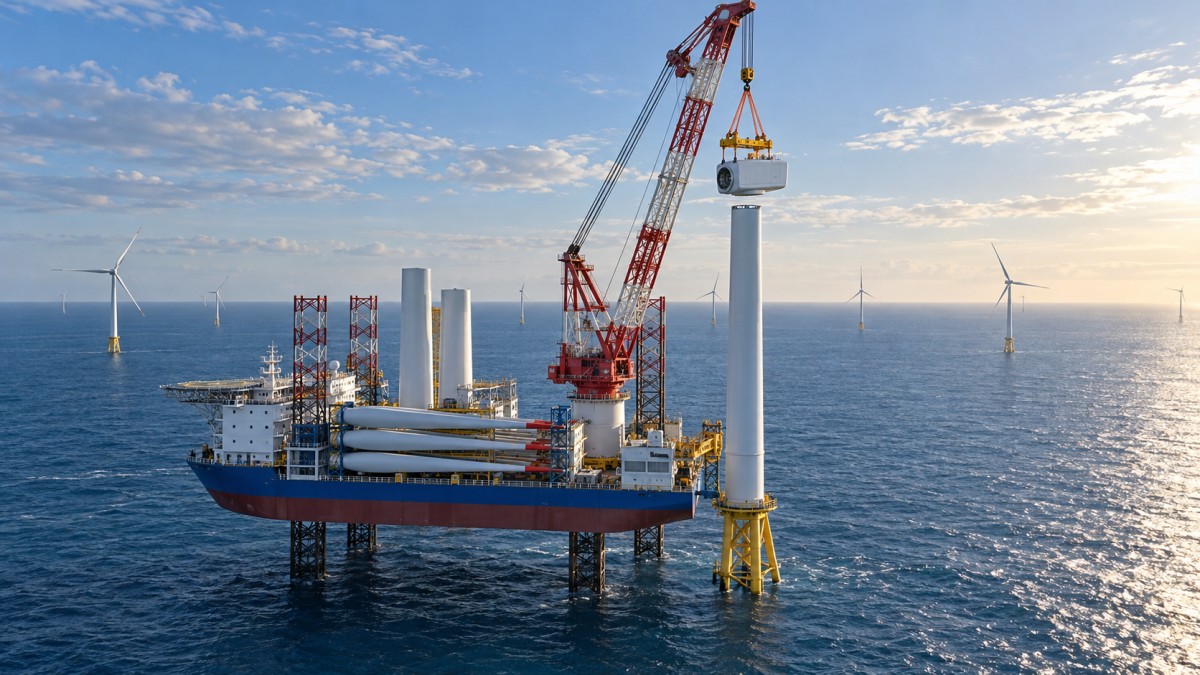
A useful early test is to sketch the most demanding lift using the actual vessel arrangement: deck position, crane radius, hook height, rigging length, installation elevation and exclusion zones. If those inputs are provisional, record the assumptions and repeat the check when the turbine supplier issues updated drawings.
The vessel choice depends on more than the crane
Jack-up installation vessels provide an elevated working platform and are widely used for fixed-bottom turbine installation. Their suitability depends on water depth, air gap, leg length, seabed conditions and the ability to achieve the required foundation support. Geotechnical assessment and site-specific leg penetration analysis are essential; a vessel that can work at the water depth may still face restrictions caused by the seabed.
Floating heavy-lift vessels avoid the need to jack up but introduce vessel motion and station-keeping considerations during lifts and mating operations. Whether a floating method is viable depends on the equipment, turbine supplier’s tolerances, lifting arrangement and forecast conditions. It should be assessed as a complete engineered method rather than treated as a direct substitute for a jack-up.
Deck capacity can be just as decisive as lifting capacity. Larger tower sections and longer blades consume space in ways that gross deck area alone does not reveal. Sea-fastening points, access routes, crane sweep, weight distribution and component separation all influence how many complete turbine sets can be carried. A vessel able to lift every component may still require more port returns than assumed in the original schedule.
Some projects consider feeder arrangements, in which components are transported to an offshore installation vessel rather than carried from port by that vessel. This may reduce installation-vessel transit, but it adds offshore transfer interfaces and weather-sensitive operations. The calculation must include feeder availability, component handover, simultaneous operations and the consequences of a delayed delivery—not just days saved in transit.
Ports and component handling can set the real limit
A turbine that fits the vessel may not fit the intended marshalling port. Longer blades need suitable storage and transport paths; heavier nacelles and tower sections require adequate quay and ground-bearing capacity. Turning areas, overhead obstructions, berth depth, tidal range and access for transport equipment all need to be checked against the proposed delivery and loadout method.
The interface between manufacturing delivery and offshore loadout deserves attention. Components may arrive before the installation vessel is ready, creating storage, preservation and inspection requirements. Conversely, insufficient laydown space can force just-in-time delivery, exposing the vessel schedule to factory or transport delays. A port plan should show not only where components sit, but how they move without blocking other loads or operations.
Lifting tools, blade cradles and sea fastenings are also project equipment with their own engineering and delivery lead times. Their compatibility should be confirmed across the turbine manufacturer, port contractor and vessel operator. If responsibility for a damaged component changes at loadout, the inspection and acceptance point needs to be clear in the contracts.
Weather windows and sequence: the limiting operation matters
Larger components can change both the duration and the allowable conditions of an operation. Wind affects suspended blades and their alignment; waves and vessel motion can constrain transfers or floating lifts; visibility and access may affect associated work. The governing limit is the most restrictive applicable limit for the task and configuration, not a single generic weather threshold for the vessel.
A weather window must cover the planned operation and any required contingency or safe stopping action. For example, the team should know what happens if a blade cannot be aligned after it has been lifted: can it be returned safely to its support, held within approved limits, or secured by another agreed method? The answer affects both the procedure and the window needed before starting.
Comparing installation scenarios requires consistent assumptions. A weather analysis should identify the location, historical period, data source, time resolution, operating limits and duration of each activity. Results based on different seasons or different definitions of downtime are not directly comparable. Schedule contingency should also reflect sequential dependencies: an incomplete tower or nacelle installation can delay work that follows, even if the next crew and equipment are available.
Foundation and floating systems change the interfaces
A larger turbine can change the loads transferred to its support structure, but foundation sizing cannot be inferred from turbine rating alone. Water depth, ground conditions, environmental loads, structural design and turbine characteristics all matter. The installation team should check foundation elevation, flange tolerances, access arrangements and the readiness of the transition piece or other interface before committing to the turbine sequence.
For floating wind, the method may shift substantially. Some concepts assemble the turbine on its floating platform in sheltered waters before towing the unit to site; others may use different assembly and offshore integration strategies. Larger rotors and higher towers can affect quayside crane reach, assembly stability, tow-out clearance and temporary support arrangements. Water depth and channel geometry at the assembly location can be as consequential as conditions at the final site.
Tow-out and hook-up introduce their own dependencies: moorings, anchors, connection equipment, tugs and cable interfaces must be ready in the right sequence. A sheltered assembly strategy may reduce certain offshore lifts, but it does not remove weather exposure or the need to engineer each transition between port, tow and final position.
Standards, verification and procurement decisions
Installation planning must align with the applicable turbine manufacturer’s instructions, vessel and crane requirements, lifting-equipment rules, marine procedures and local regulatory obligations. Depending on the project and contractual framework, standards and guidance from organisations such as IEC, ISO and DNV may be relevant. The project should identify the specific documents, editions and scope that apply rather than assume a standard name alone establishes compliance.
Independent verification or marine warranty review may also be required by contracts, insurers or project arrangements. Teams should establish the review scope and submission dates early: lift plans, vessel suitability assessments, sea-fastening designs, geotechnical studies and weather criteria can all require input from different parties. Approval of one element does not resolve an unchecked interface elsewhere.
Before reserving a vessel or finalising a port, project managers should ask suppliers to identify which turbine dimensions and masses are firm, which are provisional, and how changes will be managed. Vessel proposals should state the assumed crane configuration, deck arrangement, operating limits, mobilisation period and any upgrades still to be completed. Port offers should define bearing capacity, storage space, loadout responsibilities and the scope of any modifications.
OffshoreWire’s proposed reporting approach is built around this kind of distinction: separating an announced capability from one demonstrated under relevant operating conditions, and tracking the dependencies that remain before delivery. For an installation strategy, the practical next step is an interface review using a common, dated set of turbine, vessel, port and site assumptions. The most valuable outcome is often not a preferred vessel, but an early understanding of which unresolved parameter could invalidate the plan.
Tag
Recommended for You
{item.title}
News Categories
Leave Us a Message